Key Scientific Issues in the Manufacturing of a Reactor Coolant Pump
Key Scientific Issues in the Manufacturing of a Reactor Coolant Pump
Sub-project: Safety assessment of the rotor components
Overview
This is a government funded research project, a relatively larger one. Our research group mainly took part in the sub-project “Safety assessment of the rotor components”.
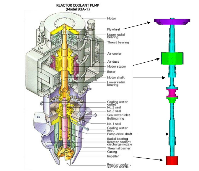
The target reactor coolant pumps (RCP) fall into two categories, which we gave them fancy names as: shaft seal RCP[1] and canned motor RCP[2].


We were doing research aiming at these two kinds of RCPs. The tasks of this sub-project include
- Rotordynamics.
- Mechanical issues about the flywheel.
- Cracks on shaft due to mechanical and thermal loads.
- Electromagnetic properties of the motor.
My tasks
The tasks assigned to me are mostly about the rotordynamics of the RCPs, particularly the experimental study. A model pump was designed by myself and its rotordynamics was tested. I also developed a Matlab code to calculate the supporting effects of running clearances in a pump and to solve the rotordynamics characteristics of the RCP.
The experimental work mainly focused on the vibration of the pump rotor. I measured the trajectory of the rotor, recorded the vibration level on the supporting structure and bearing housing. The model pump is actually designed based on a canned motor pump. Unlike a conventional canned motor pump which circulates its internal flow by an auxiliary impeller, the model pump had its internal flow propelled by an external fluid source. In this way, we could control the flow rate inside the clearances between the rotor and stator and study the influences of this internal flow on the rotordynamics of the pump.
The rotor trajectory was measured by water proof eddy current displacement sensors. And the vibrating acceleration was tested by piezoelectic transducers. The above dynamic data was recorded by a data acquisition hardware of NI and was facilitated by a LabView code. The measured data was processed by Matlab scripts to realize automatic analyzing.
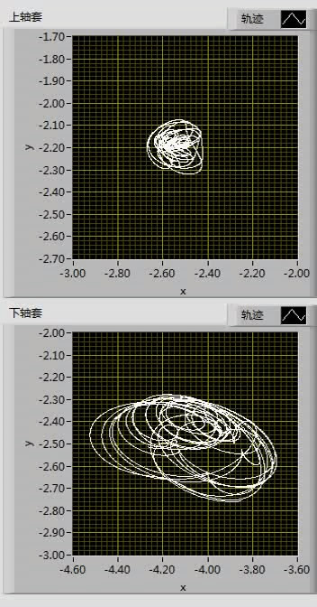
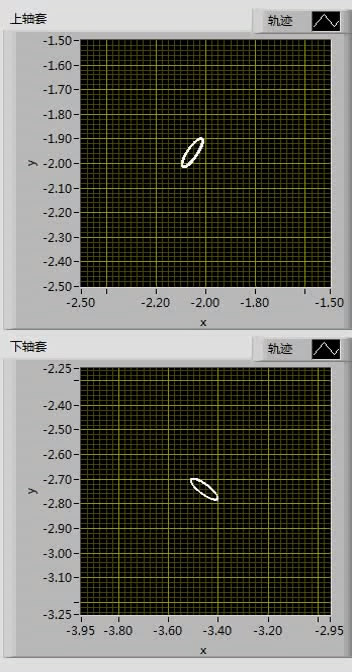
The following movies are the recorded rotor trajectories by LabView. The first is a stable rotor motion and the second is an unstable one.
(Click the image to link to the movie.)
(Click the image to link to the movie.)
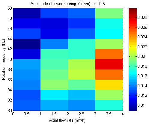
For experiment configuration which produced stable rotor motion, the effects of internal flow on the vibration amplitude of the rotor was studied. The following figure shows the measured vibration amplitudes of the rotor under various internal flow rates and rotating speeds. This figure tells us that the vibration level rises as the axial flow becomes larger. The amplitudes rise and then fall with increasing rotating speed. The later phenomenon is the combination of the unbalanced excitation and the supporting of the internal running clearances inside the model pump. At first, when the rotating speed is relatively low, the supporting effect of the running clearances is weak. The vibration goes up with speed. After a certain speed point, the supporting effects of the running clearances come into play. Then the vibration is restricted after reaching a maximum point.


