Safety Analysis of a Main Feedwater Pump in the Secondary Loop of a Nuclear Power Plant
Overview
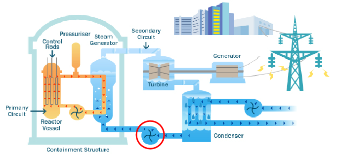
The feedwater pump under question is the pump unit of the secondary loop/circuit for a pressurized water nuclear reactor system (PWR). In a typical PWR system the feedwater pump is used to deliver water to the steam generator as illustrated in the following figure[1] and enclosed with a red circle. The water transforms into steam and then drive the steam turbine to generate power in terms of electricity.
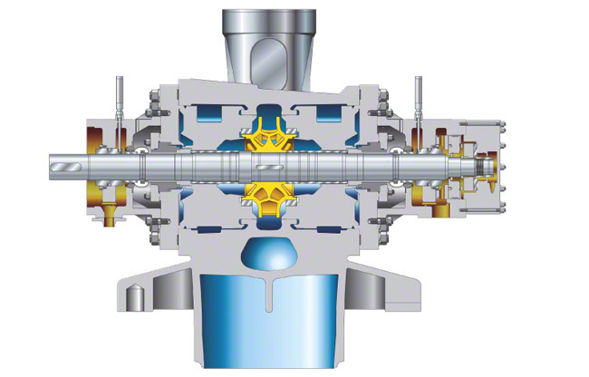
The feedwater pump is a single stage double suction centrifugal pump and is very similar to the figure below[2]. Our team were required to do a series of analysis focusing on the safety of the pump. The analysis included thermal stress analysis, seismic response analysis and rotor dynamic analysis.
Tasks and Results
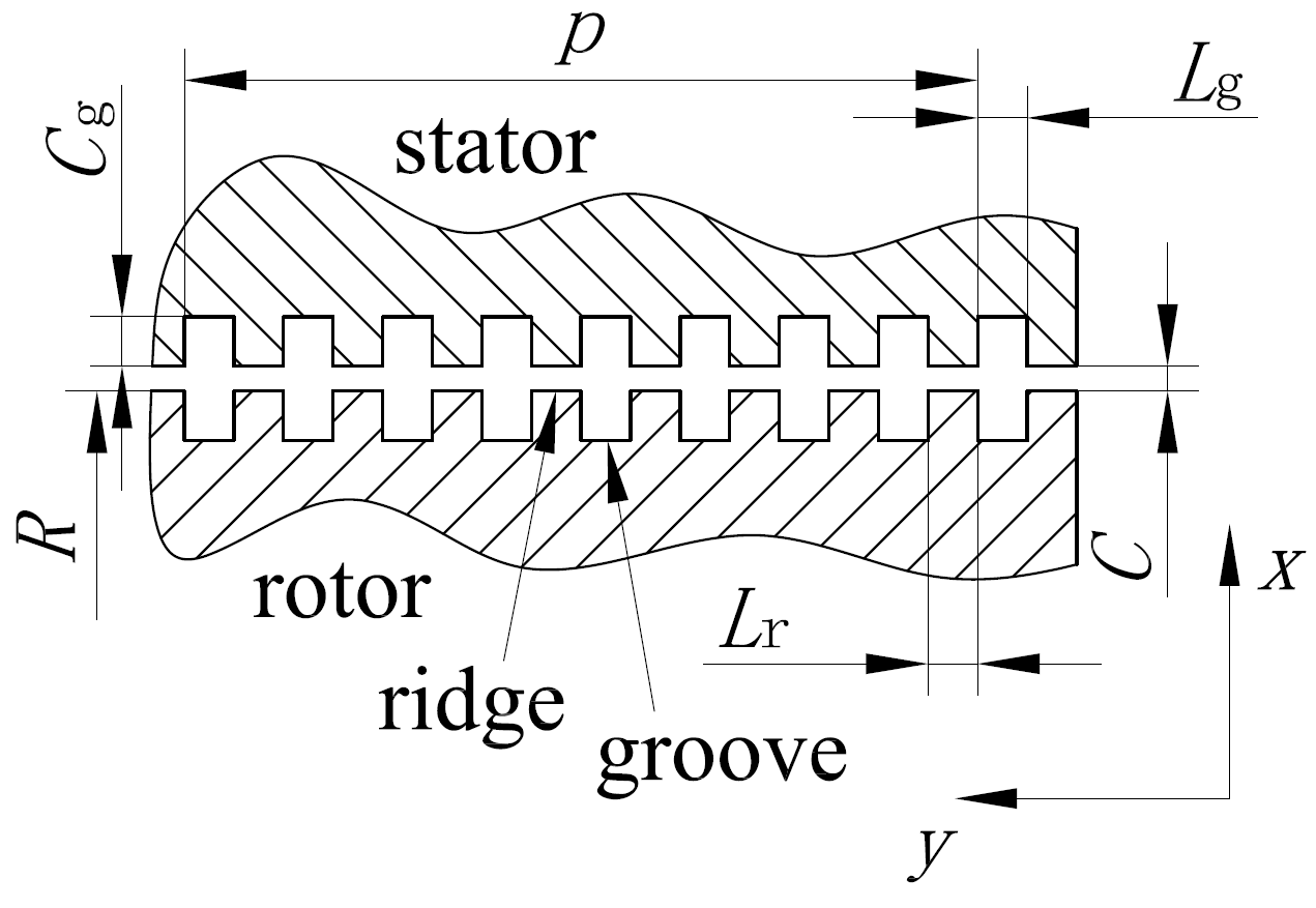
Again I was designated to conduct the rotordynamic analysis. For rotordynamic characteristics of the feedwater pump is affected by the fluid in the running clearances between the pump rotor and stator. Those running clearances are designed to be helically grooved annular seals. Lots of efforts were taken to evaluate the resistance characteristics of those seals, in order to calculate their supporting stiffness and damping effects. The above mentioned evaluation were done by using ANSYS CFX. The geometry and some boundary conditions are shown in the following figures.
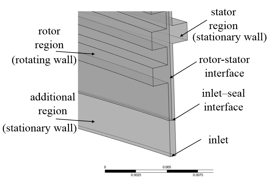
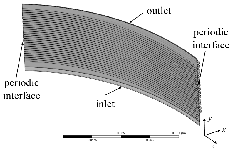
The grid was created by ICEM, all hexahedra.

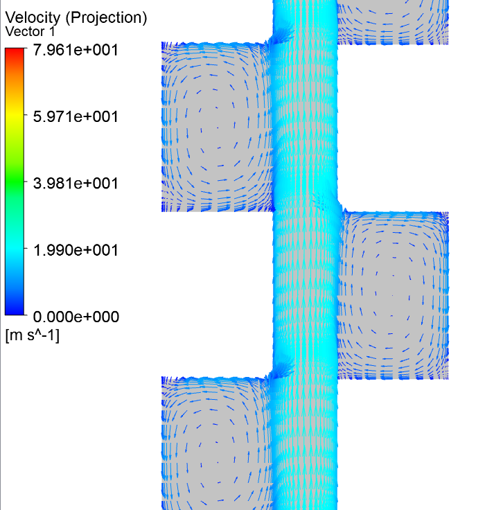
A typical velocity vector field inside the clearance is shown in the following figure.
The major outcome of the CFD simulations is the resistance coefficients associated to different clearance widths and rotating speeds. These results are summarized in the following figure. From this figure we can see that, if the rotating speed is fixed, the resistance of the helically grooved annular seal is hardly affected when the clearance width is larger than 1 mm. Generally, higher speed means larger resistance.
